Extra exam question E7D08
Subelement E7, PRACTICAL CIRCUITS· Group E7D
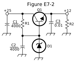
What type of circuit is shown in Figure E7-2?
- A.Switching voltage regulator
- B.Common emitter amplifier
- C.Linear voltage regulator (correct answer)
- D.Common base amplifier
WhyFigure E7-2 shows a linear voltage regulator circuit. Figure E7-2 shows a linear voltage regulator: a series-pass transistor (Q1) controlled by a Zener reference (D1) continuously adjusts its conduction to hold a steady DC output voltage, the classic series-pass linear regulator topology, with no switching or chopping elements present, answer C. It isn't a switching regulator (no inductor or PWM switching element is present), and it isn't simply a common emitter or common base amplifier, those describe general-purpose amplifier configurations, not this specific voltage-regulating circuit.
Published 2026-08-28 · Last updated 2026-08-28 · Question text is verbatim from the 2024-2028 NCVEC Element 4 pool (public domain); the explanation above is original writing, see our methodology.
Related questions
- E7D01How does a linear electronic voltage regulator work?
- E7D02How does a switchmode voltage regulator work?
- E7D03What device is used as a stable voltage reference?
- E7D04Which of the following describes a three-terminal voltage regulator?
- E7D05Which of the following types of linear voltage regulator operates by loading the unregulated voltage source?