Extra exam question E7D07
Subelement E7, PRACTICAL CIRCUITS· Group E7D
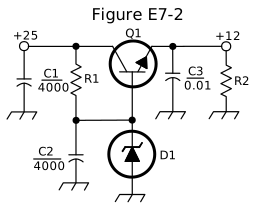
What is the purpose of C2 in the circuit shown in Figure E7-2?
- A.It bypasses rectifier output ripple around D1 (correct answer)
- B.It is a brute force filter for the output
- C.To prevent self-oscillation
- D.To provide fixed DC bias for Q1
WhyIn the circuit shown in Figure E7-2, C2 bypasses rectifier output ripple around D1. In Figure E7-2, C2 is connected across D1, the Zener reference diode, and bypasses rectifier output ripple around D1, keeping ripple on the unregulated input from disturbing the clean, stable reference voltage that sets the regulator's output, answer A. It isn't a brute-force output filter (that role, if present, would sit at the actual output), isn't there to prevent self-oscillation, and doesn't provide fixed DC bias for Q1 by itself, that's the combined job of the R1/D1 reference network.
Published 2026-08-28 · Last updated 2026-08-28 · Question text is verbatim from the 2024-2028 NCVEC Element 4 pool (public domain); the explanation above is original writing, see our methodology.
Related questions
- E7D01How does a linear electronic voltage regulator work?
- E7D02How does a switchmode voltage regulator work?
- E7D03What device is used as a stable voltage reference?
- E7D04Which of the following describes a three-terminal voltage regulator?
- E7D05Which of the following types of linear voltage regulator operates by loading the unregulated voltage source?