Extra exam question E7D06
Subelement E7, PRACTICAL CIRCUITS· Group E7D
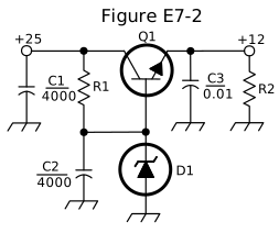
What is the purpose of Q1 in the circuit shown in Figure E7-2?
- A.It provides negative feedback to improve regulation
- B.It provides a constant load for the voltage source
- C.It controls the current to keep the output voltage constant (correct answer)
- D.It provides regulation by switching or “chopping” the input DC voltage
WhyIn the circuit shown in Figure E7-2, Q1 controls the current to keep the output voltage constant. In Figure E7-2, Q1 is the series-pass transistor: it sits between the unregulated +25 volt input and the regulated +12 volt output, and its conduction is continuously adjusted to control the current flow and keep that output voltage constant despite changes in load or input voltage, answer C. It isn't itself providing negative feedback (that's part of the overall regulator loop, not Q1's individual role), isn't acting as a constant load, and this is a linear, not switching, regulator, so Q1 isn't chopping the input voltage.
Published 2026-08-28 · Last updated 2026-08-28 · Question text is verbatim from the 2024-2028 NCVEC Element 4 pool (public domain); the explanation above is original writing, see our methodology.
Related questions
- E7D01How does a linear electronic voltage regulator work?
- E7D02How does a switchmode voltage regulator work?
- E7D03What device is used as a stable voltage reference?
- E7D04Which of the following describes a three-terminal voltage regulator?
- E7D05Which of the following types of linear voltage regulator operates by loading the unregulated voltage source?