Extra exam question E6A11
Subelement E6, CIRCUIT COMPONENTS· Group E6A
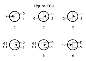
In Figure E6-1, which is the schematic symbol for a P-channel junction FET?
- A.1 (correct answer)
- B.2
- C.3
- D.6
WhySymbol 1 in Figure E6-1 is the schematic symbol for a P-channel junction FET. In Figure E6-1, symbol 1 shows a single gate lead with the arrow pointing outward, away from the channel bar, and no separate insulated-gate bar, the standard symbol for a P-channel junction FET, an outward-pointing arrow indicating P-channel and the absence of the extra insulated-gate line distinguishing a JFET from a MOSFET, answer A. Symbol 2 is an N-channel MOSFET, symbol 3 is a P-channel MOSFET, and symbol 6 is an N-channel JFET (arrow pointing inward instead), none of which is the P-channel JFET being asked for.
Published 2026-08-28 · Last updated 2026-08-28 · Question text is verbatim from the 2024-2028 NCVEC Element 4 pool (public domain); the explanation above is original writing, see our methodology.
Related questions
- E6A01In what application is gallium arsenide used as a semiconductor material?
- E6A02Which of the following semiconductor materials contains excess free electrons?
- E6A03Why does a PN-junction diode not conduct current when reverse biased?
- E6A04What is the name given to an impurity atom that adds holes to a semiconductor crystal structure?
- E6A05How does DC input impedance at the gate of a field-effect transistor (FET) compare with that of a bipolar transistor?