General exam question G7A13
Subelement G7, PRACTICAL CIRCUITS· Group G7A
G7A13
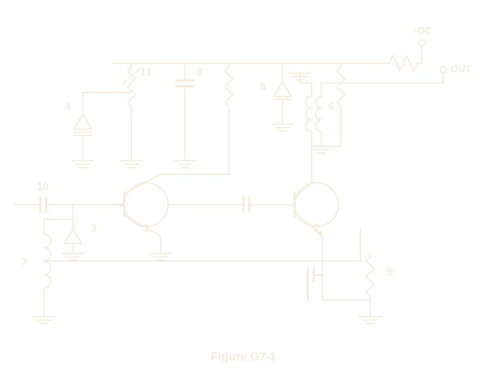
Which symbol in Figure G7-1 represents a tapped inductor?
- A.Symbol 7 (correct answer)
- B.Symbol 11
- C.Symbol 6
- D.Symbol 1
WhySymbol 7 in figure G7-1 represents a tapped inductor. In figure G7-1, symbol 7 is drawn as a coil with a horizontal wire branching off partway down its winding, the schematic convention for a tapped inductor, answer A. Symbols 1, 6, and 11 represent other components in the figure, none carrying that mid-winding tap.
Published 2026-08-28 · Last updated 2026-08-28 · Question text is verbatim from the 2023-2027 NCVEC Element 3 pool (public domain); the explanation above is original writing, see our methodology.
Related questions
- G7A01What is the function of a power supply bleeder resistor?
- G7A02Which of the following components are used in a power supply filter network?
- G7A03Which type of rectifier circuit uses two diodes and a center-tapped transformer?
- G7A04What is characteristic of a half-wave rectifier in a power supply?
- G7A05What portion of the AC cycle is converted to DC by a half-wave rectifier?