Extra exam question E7G07
Subelement E7, PRACTICAL CIRCUITS· Group E7G
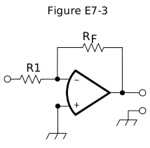
What voltage gain can be expected from the circuit in Figure E7-3 when R1 is 10 ohms and RF is 470 ohms?
- A.0.21
- B.4700
- C.47 (correct answer)
- D.24
WhyThe circuit in Figure E7-3 with R1 at 10 ohms and RF at 470 ohms has a voltage gain of 47. The Figure E7-3 circuit is an inverting op-amp amplifier, whose voltage gain magnitude equals the feedback resistor divided by the input resistor: 470 ohms divided by 10 ohms works out to a gain of 47, answer C. The other listed figures come from inverting the ratio, misplacing a decimal point, or otherwise miscalculating that same RF-over-R1 division.
Published 2026-08-28 · Last updated 2026-08-28 · Question text is verbatim from the 2024-2028 NCVEC Element 4 pool (public domain); the explanation above is original writing, see our methodology.
Related questions
- E7G01What is the typical output impedance of an op-amp?
- E7G02What is the frequency response of the circuit in E7-3 if a capacitor is added across the feedback resistor?
- E7G03What is the typical input impedance of an op-amp?
- E7G04What is meant by the term “op-amp input offset voltage”?
- E7G05How can unwanted ringing and audio instability be prevented in an op-amp audio filter?