Extra exam question E7B12
Subelement E7, PRACTICAL CIRCUITS· Group E7B
E7B12
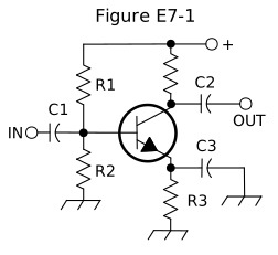
What type of amplifier circuit is shown in Figure E7-1?
- A.Common base
- B.Common collector
- C.Common emitter (correct answer)
- D.Emitter follower
WhyFigure E7-1 shows a common emitter amplifier circuit. Figure E7-1 shows a common emitter amplifier: the input signal enters at the base (through C1), and the output is taken from the collector (through C2), with the emitter resistor R3 providing the bias stabilization typical of this configuration, answer C. It isn't common base (input at the emitter) or common collector/emitter follower (output taken from the emitter instead of the collector).
Published 2026-08-28 · Last updated 2026-08-28 · Question text is verbatim from the 2024-2028 NCVEC Element 4 pool (public domain); the explanation above is original writing, see our methodology.
Related questions
- E7B01For what portion of the signal cycle does each active element in a push-pull, Class AB amplifier conduct?
- E7B02What is a Class D amplifier?
- E7B03What circuit is required at the output of an RF switching amplifier?
- E7B04What is the operating point of a Class A common emitter amplifier?
- E7B05What can be done to prevent unwanted oscillations in an RF power amplifier?