Extra exam question E7B11
Subelement E7, PRACTICAL CIRCUITS· Group E7B
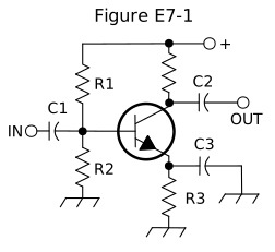
In Figure E7-1, what is the purpose of R3?
- A.Fixed bias
- B.Emitter bypass
- C.Output load resistor
- D.Self bias (correct answer)
WhyIn Figure E7-1, R3 provides self bias. In Figure E7-1, R3, connected between the emitter and ground, is the self-bias (emitter bias) resistor: as collector current tends to rise with temperature or from transistor-to-transistor variation, the resulting increase in emitter current raises the voltage across R3, which reduces the base-emitter forward bias and pulls current back down, a built-in negative-feedback stabilizing action, answer D. It isn't fixed bias, isn't specifically an emitter bypass component (that's C3's job, bypassing R3 for AC signals), and isn't the output load resistor, that's a separate connection at the collector.
Published 2026-08-28 · Last updated 2026-08-28 · Question text is verbatim from the 2024-2028 NCVEC Element 4 pool (public domain); the explanation above is original writing, see our methodology.
Related questions
- E7B01For what portion of the signal cycle does each active element in a push-pull, Class AB amplifier conduct?
- E7B02What is a Class D amplifier?
- E7B03What circuit is required at the output of an RF switching amplifier?
- E7B04What is the operating point of a Class A common emitter amplifier?
- E7B05What can be done to prevent unwanted oscillations in an RF power amplifier?