Extra exam question E5C11
Subelement E5, ELECTRICAL PRINCIPLES· Group E5C
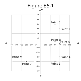
Which point in Figure E5-1 best represents the impedance of a series circuit consisting of a 300-ohm resistor and an 18-microhenry inductor at 3.505 MHz?
- A.Point 1
- B.Point 3 (correct answer)
- C.Point 7
- D.Point 8
WhyA series circuit consisting of a 300-ohm resistor and an 18-microhenry inductor at 3.505 MHz plots at Point 3 on Figure E5-1. An 18-microhenry inductor at 3.505 MHz has an inductive reactance of 2 pi times 3.505 MHz times 18 microhenries, which works out to about 400 ohms, so the series combination of a 300-ohm resistor and this inductor plots at R equals 300 ohms, X equals positive 400 ohms on Figure E5-1, the coordinates matching Point 3 on the chart, answer B. None of the other labeled points sit at that specific resistance and positive-reactance combination.
Published 2026-08-28 · Last updated 2026-08-28 · Question text is verbatim from the 2024-2028 NCVEC Element 4 pool (public domain); the explanation above is original writing, see our methodology.
Related questions
- E5C01Which of the following represents pure capacitive reactance of 100 ohms in rectangular notation?
- E5C02How are impedances described in polar coordinates?
- E5C03Which of the following represents a pure inductive reactance in polar coordinates?
- E5C04What type of Y-axis scale is most often used for graphs of circuit frequency response?
- E5C05What kind of diagram is used to show the phase relationship between impedances at a given frequency?